After selecting a 2Dsimplification assumption, the workflow for solving the problem is similar for all options. You use the 2Dsimplification option when defining a static, nonlinear, thermal, pressure vessel design, and design studies on qualifying 3D models.
This article will cover the different types of 2Dsimplification analysis available for the static and nonlinear study modules in SOLIDWORKS Simulation.
Block diagram blocks can be connected in three basic forms: Cascade. Parallel. Feedback. We’ll next look at each of these forms and derive a single- block equivalent for each. K. Webb ESE 430. 5. Cascade Form. Blocks connected in cascade:
The following example first reads a set of input points and masses from an ASCII file. Using two property maps, the points and their initial mass are passed to the Reconstruction_simplification_2 object.
Learn how to solve block diagram reduction problems with step-by-step solutions. Understand the concept and techniques of block diagram reduction to simplify complex systems.
In this example, we will examine a block diagram of a SISO system and demonstrate how to use block diagram reduction techniques to simplify the system. Let’s consider the following block diagram:
Explore block diagramsimplificationexamples to enhance your understanding of circuit simplification techniques, including simplifying parallel and series paths, applying Kirchhoff's laws, and using thevenin and Norton equivalents.
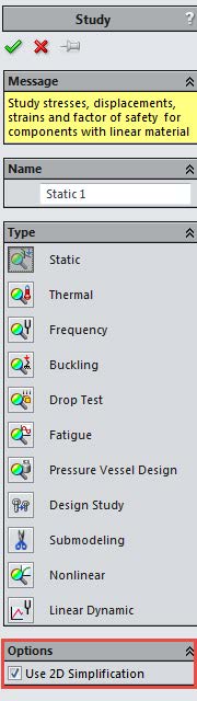
2DSimplification option in SOLIDWORKS Simulation is available when defining static linear, nonlinear, thermal, pressure vessel and design studies on qualifying 3D models.
Start with an open document. Create a new Simulation study (static, thermal, or nonlinear). In the Study PropertyManager, under Options, select Use 2DSimplification. Select one of the available options. Use this option for thin geometries where one dimension is much smaller than the other two.
 This article will cover the different types of 2D simplification analysis available for the static and nonlinear study modules in SOLIDWORKS Simulation.